Speaker Layouts and Room Calibration
A surround mix is only as reliable as the room where you make it. Speaker placement, level, delay, and frequency response all affect what you hear at the mix position. Calibration gives you a repeatable reference for judging balance and checking whether a mix will translate to another system.
The 7.1 layout
Our room has seven independent main channels and an LFE channel. Its placement reference is ITU-R BS.2051-3, Table 11, Sound System I , on printed page 14, PDF page 16. The document calls this 0+7+0: seven middle-layer speakers, with no upper or lower speakers. LFE is listed separately. BS.775’s Figure 2 describes speakers sharing surround channels; BS.2051’s System I covers our independent side and rear channels.
The table gives the allowed horizontal angles and our chosen setup targets. The targets are convenient starting points within the allowed ranges.
| Speaker | ITU angle range from straight ahead | Our setup target |
|---|---|---|
| Center | 0° | 0° |
| Front left | 30°–45° left | 30° left |
| Front right | 30°–45° right | 30° right |
| Side left | 85°–110° left | 90° left |
| Side right | 85°–110° right | 90° right |
| Rear left | 120°–150° left | 135° left |
| Rear right | 120°–150° right | 135° right |
Check the speaker placement
Use masking tape, string, a tape measure, and a large protractor. Keep a shared log of the results.
- Make a small cross on the floor with two short pieces of masking tape, directly below where your head would be when seated at the mix position. The intersection marks the listening position.
- Establish straight ahead. Lay a straight strip of masking tape on the floor from the cross toward the point directly beneath the center speaker. Use a taut string as a guide to keep the strip straight. This strip marks the 0° direction. Directly beside you is 90°; directly behind you is 180°. These are directions for reading the protractor, not additional speaker targets.
- Measure each speaker’s horizontal angle. Center the protractor on the listening mark with its 0° line pointing forward. Stretch a taut string along the floor from the mark toward the point beneath the speaker’s acoustic center. Read the angle from the forward line and record it with its left or right designation. Repeat for all seven speakers and compare the results with the table.
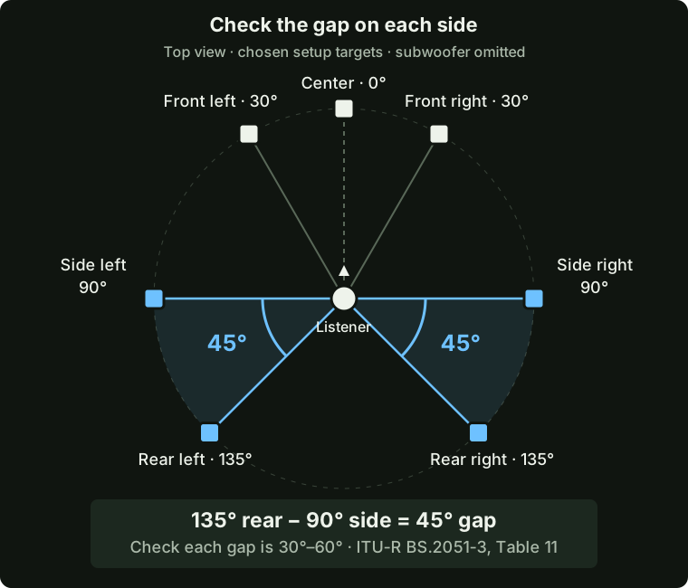
- Check the side-to-rear gap on each side. Subtract the side angle from the rear angle, using positive angle magnitudes. Table 11 allows 30°–60° for each gap. The diagram shows 135° − 90° = 45°. A side at 110° and a rear at 120° would pass their individual ranges but fail this check because they are only 10° apart. Record both gaps.
- Check height and aim. Table 11 specifies 0° elevation for all seven main speakers, so their acoustic centers should be at seated ear height. Aim each cabinet at the listening position. Rotating a cabinet changes its aim, not the placement angle you recorded in step 3.
- Record the distance from seated ear position to each speaker’s acoustic center. Similar distances are preferable; unequal sound arrival times need delay compensation in the monitoring system.
- Note any needed adjustments on your layout sketch. After moving a speaker, recheck its angle, height, distance, and any affected surround gap. Once placement is settled, continue with channel-level alignment below.
Align the channel levels
Use the same test signal and measurement settings for every channel:
- Prepare the test signal in REAPER. On an empty two-channel track, insert
JS: Pink Noise Generatorin Mono mode, followed byJS: Loudness Meter Peak/RMS/LUFS (Cockos). In the meter’s settings, enable RMS momentary and RMS integrated, which are off by default, and turn on Force mono analysis for this duplicated mono signal. Start playback and adjust the generator’s output until RMS-I settles near -20 dBFS. Reset the meter after each adjustment so the average excludes the previous level. Use the RMS reading for this check; peak and LUFS measure different things. Dolby’s calibration guidance assumes its Renderer noise; this is our approximate reference when using another generator. - Route one copy of that mono signal to one full-range speaker at a time. Keep the track fader and send gain at 0 dB, and avoid summing the track’s left and right copies into the same output. Once the test level is set, leave the generator unchanged for the remaining channels.
- Place an SPL meter at the mix position and at seated ear height. Set it to C weighting and Slow response. The NIOSH Sound Level Meter app supports both settings, although a calibrated measurement microphone is more accurate.
- Adjust the input-level control on the speaker until the SPL meter reaches the chosen reference level. Repeat for all seven full-range speakers. Keep the test signal, REAPER faders, send gains, and interface output settings fixed while making these adjustments.
After alignment, photograph or record each speaker’s input-level setting and save the REAPER calibration project. Record the interface output settings too, including any levels set in its control software. Together, these settings let everyone reproduce the calibrated playback level.
Leave the individual speaker controls at their calibrated settings. For quieter work, reduce all seven main playback channels by the same amount using a software monitoring control that reaches every output. Include the subwoofer output in that change to preserve the balance. Restore the recorded settings for reference checks.
LFE and bass management
The subwoofer may reproduce two different signal paths:
- The LFE channel contains material that the mixer sends to the
.1channel. - Bass management redirects low frequencies from speakers that cannot reproduce them. The crossover belongs to the monitoring system, not the mix.
Do not treat these paths as interchangeable. The main channels should contain their intended low-frequency content whether or not the playback system uses bass management. The LFE channel is an additional effects channel, not a replacement for bass in the main speakers.
Check the LFE level
Use the SPL meter for this lab. The LFE target is about 4 to 6.5 dB above the main-speaker reference, not 10 dB above its overall SPL reading. The difference is smaller because the subwoofer reproduces fewer frequencies.
- Leave the seven main-speaker settings unchanged. Keep the SPL meter at the listening position with C weighting and Slow response.
- Send LFE calibration noise through the LFE channel alone. Keep the REAPER signal level fixed. If you use the pink-noise generator, route it through the system’s LFE filter and do not raise its level after filtering.
- Add 4 to 6.5 dB to the main-speaker reference. For example, if the mains are set to 80 dBC, aim for 84 to 86.5 dBC from the LFE channel.
- Adjust the subwoofer’s input-level control until the SPL meter reaches that range. Record the final setting.
Dolby’s music-studio guidance gives 89 to 91.5 dBC for LFE when the main speakers are set to 85 dBC. Our calculation applies that same difference to the lower level used in this room. Treat it as a practical approximation. If an RTA is available, use it to check that the LFE is 10 dB higher than the center speaker in the bass bands they share.
If the subwoofer also reproduces bass redirected from the main speakers, use an LFE-channel trim instead of changing the subwoofer’s input control. This keeps the redirected bass at its calibrated level.
Reference level and hearing safety
Calibration uses C-weighted measurements. Hearing exposure is measured differently, using A weighting over time. Use the reference level only for brief checks. Work quieter for routine editing and take regular breaks.